top of page
新旧厂区
搜尋
作家相片: Zhengzhou SmartGenZhengzhou SmartGen
0

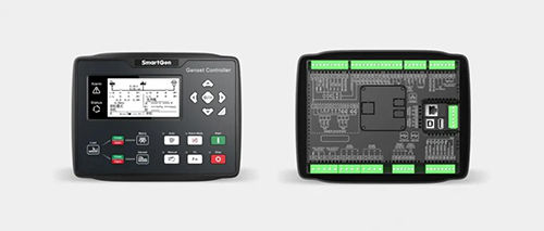
In the previous three chapters, we respectively introduced the powerful display features of HGM9420N/LT (with 16 built-in languages), as well as the various extension, synchronization switching, communication protocol customization, NEL((non essential load), dummy load, cloud monitoring, etc. This chapter we will introduce the PLC function of the control module.

The PLC editing interface is shown as follows

1

PLC elements: condition elements, action elements, settings and other areas

1. The conditional elements are shown in the following table

2

2. The action elements are shown in the following table

3

3. Setting and other areas

4

Logic Introduction

1. “Or” logic diagram


Description: either the input port 1 or the input port 2 is effective, the mark 1 is set to 1; otherwise the mark 1 is set to 0.

2. “And” logic diagram


Description: when the control module is in manual mode and the input port 1 is effective, mark 2 is set to 1 and the timer 1 begins to counting; Otherwise mark 2 is set to 0, timer 1 reset.

3. Combinational logic example diagram


Description: either “input port 1” or “input port 2” is effective, and “normal output of power generation” is effective, triggering ” performance function 1″.

Applicaion Examples

Example 1: Engie Oil Prelubrication Engine Oil prelubrication function requirements: when it is standby, output 0.5 hour, stop output 0.5 hour; output during preheating, not during other periods.

1. The PLC logic diagram is as follows
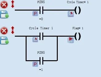

8

Description: P295 engine state parameter, 0: stands for “standby”; 1: stands for “preheating”.

2. The settings of the control module output ports are as follows

9

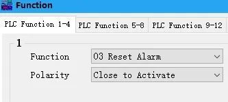
Example 2: Automatic clear stop alarm Requirements: when the genset is in automatic mode, after the remote start (on-load) input is disconnected, it will automatically clear the alarm.

1. The PLC logic diagram is as follow

10
10-1

2. The control module input port is set as follows

11

Example 3: Modify the configuration parameters of successful crank conditions Requirements: the successful crank condition of the unit is power generation + oil pressure. For the first start, the crank condition should be changed to power generation because crank cannot be judged accurately according to the oil pressure. For the second or the third start, the crank condition should be changed to power generation + oil pressure.

1. The PLC logic diagram is as follows

12

2. Description of successful crank

13

Example 4: Mutiple fans control Requirements: when the percentage of the unit’s on-load power is less than 20% and the engine temperature is greater than 60℃, Fan 1 outputs. When the percentage of the unit’s on-load power is equal or great than 20%, Fan 1 and Fan 2 output; when the percentage of the unit’s on-load power is equal or great than 40%, Fan 1, 2 and 3 output; when the unit’s on-load power percentage is equal or great than 60%, Fan 1, 2, 3 and 4 output.

1. The PLC logic diagram is as follows:
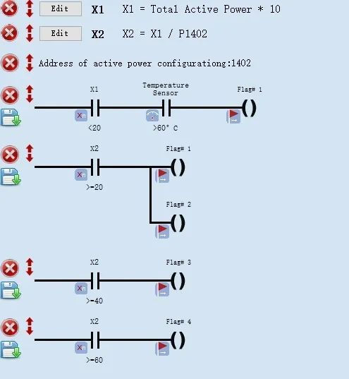
14

2. The settings of the control module output port are as follows
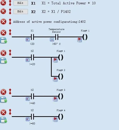
14

The PLC function of HGM9400N could also realize data acquisition and logic control with CAN interfaces modules (chargers, HAT series control modules, etc.) by customizing CAN communication configuration quantity. It will be continued… We will introduce functions and usage of the Host USB interface next time.


16
0 次查看0 則留言
作家相片: Zhengzhou SmartGenZhengzhou SmartGen
0

In the previous two chapters, we respectively introduced the powerful display features of HGM9420N/LT (with 16 built-in languages) and various extended functions. This chapter we will introduce the single unit control module’s special synchronization switching features, as well as the communication protocol customization, NEL (non essential load), dummy load, cloud monitoring and other functions.

The single unit automatic system composed of one mains supply and one genset could realize the synchronous swithing beween power generation and mains supply, which decreases the power supply interruption to a great extend caused by power generation and mains switching.

Operation Description

Automatic start/stop Press

button, the indicator lights on, indicating that the genset is in automatic startup mode.

Automatic start: a) Mains power is normal and remote start (on-load) is effective, the unit high-speed warming-up delay ends, the indicator lights on if power generation is normal, the control module sends out switch-on signal when gensets and mians power meet the synchronization requirements, while sending out the switch-off signal immediately after detecting power switching feedback signal, then genset is on-load.

b) When the mains power starts abnormally and high-speed warming-up ends, the indicator lights on if the power generation is normal. If the voltage and frequency meet the requirements of on-load, the power generation closes and relay outputs, the genset is loaded, the power supply indicator lights on and the genset is in normal operation.

Automatic Stop: During the normal operation of the genset, if the mains power returns to normal, then enters the “mains voltage normal delay”. Make sure the mains power is normal, the indicator of mains power status will be on, the “stop delay” will begin. For another case, when the remote start input fails, “stop delay” starts.

The control module waits for gensets and the mains power to meet the synchronization requirements, it will send out the mains power closing signal. After detecting the feedback signal of mains power switch-on, it will immediately send out the mains power switch-off signal, the power supply indicator lights off, the mains power is on-load, the mains power supply indicator lights on, and the “high-speed heat dissipation delay” begins to enter the shutdown process.

The conversion flow chart is as follows

1e

Synchronous switching typical application diagram

2e

Note: Breakers (such as frame circuit breakers) that can close simultaneously should be used.

Parameter settings

3e
3-1e

Note: the control module shall be set and conected the auxiliary contact signals to power generation switch closing and mains power switch closing, so as to judge the position state of switch-on and switch-off.

Switch-on/Switch-off time and on-off state detection time

4e

Available for gas unit

5e

The position of current transformer can be defined

6e

Three non-essential loads (NEL) settings

7e

Three dummy loads settings

8e

Cloud monitoring settings

9e

Communication protocol customization

10e

It will be continued… Next chapter we will introduce the powerful built-in PLC functions of HGM9420N/LT.

11
1 次查看0 則留言
bottom of page